tensr hardware · Crimpdeq DIY kit
From bare board to your first reliable reading.
Wire your load cell, calibrate it, and check the result here. This guide covers the Crimpdeq v1 and v2 PCBs used in the DIY kit. Match the diagram to your board before connecting anything.
1. Prepare your parts and a known weight
- Your PCB, its supplied firmware/version information, and a compatible four-wire load cell, such as the cell from your WH-C100 retrofit.
- A USB-C cable, soldering iron, insulated wire, heat-shrink, and a multimeter. Start with USB power; add a compatible battery only after checking the wiring.
- A secure anchor, rope or sling, suitable connectors, and at least one known weight. A second weight helps you verify the result independently.
- The Crimpdeq app. For the web app, use Chrome or Edge on a computer with Bluetooth. If your browser cannot connect, Crimpdeq also providesnative apps.
Arrange the test so the cell carries tension through its mechanical mounting points, with the plate hanging freely just above the floor. Keep the load within the limits of the cell, anchor, rope, and connectors. The PCB and its wires must not carry the suspended weight.
2. Wire the load cell with power disconnected
Unplug USB and leave the battery disconnected. If you are reusing a scale's load cell, disconnect its four leads from the original electronics first. Use the Crimpdeq board as the cell's only excitation source.
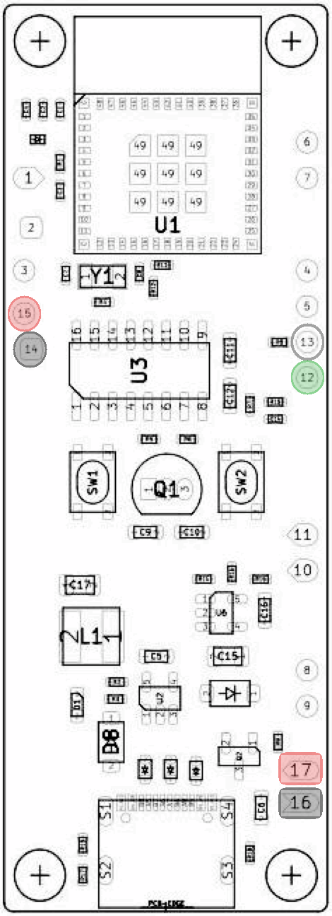
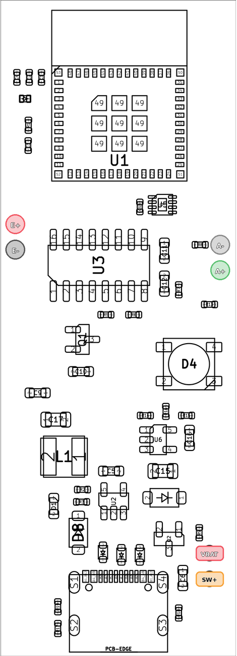
Pinout diagrams by Crimpdeq. Select an image for the full-size view. These are custom Crimpdeq PCBs; the ESP Rust development board has different connections. If your board has a different layout, contact us before wiring it.
| Cell lead | Typical color | v1 pad | v2 pad |
|---|---|---|---|
| Excitation + | Red | 15 / E+ | E+ |
| Excitation − | Black | 14 / E− | E− |
| Signal + | Green or blue | 12 / S+ | A+ |
| Signal − | White | 13 / S− | A− |
Colors are examples, not a guarantee: confirm your cell's lead functions from its documentation or original labels. Make soldered, insulated connections and secure the leads so movement cannot pull on the joints. Tape can hold or insulate a wire; it does not make dependable electrical contact.
Adding a battery and switch
Use a compatible protected, single-cell 3.7 V rechargeable LiPo pack and verify polarity. Keep both battery leads disconnected until the unpowered checks below are complete. Insulate each connection individually.
| Board | Positive path | Negative lead |
|---|---|---|
| v1 | Battery + → switch → pad 17 / B+ | Battery − → pad 16 / B− |
| v2 | Battery + → VBAT; a separate switch connects VBAT to SW+ | Battery − → E−, shared with the cell's excitation − |
On v2, VBAT remains connected to the battery with the switch off so charging can work. Keep the switch between VBAT and SW+. For the shared E− pad, use an insulated pigtail if two wires will not fit cleanly.
Before power: inspect for solder bridges; check that each cell wire reaches its intended pad and that the supply is not shorted to ground. If adding a battery, check the switch path against the table. Resolve any unexpected short or open connection, then connect power. Route and insulate the wiring inside the enclosure so it cannot be pinched or touch the PCB.
3. Power up and connect
- Leave the cell unloaded and still. Connect USB power.
- Open the Crimpdeq app, selectScan, and connect to your
Progressor_…device. Disconnect other apps using that sensor if the connection fails. - Open Measurements → Start. Gently load and release the cell; the reading should change. Its absolute value may be wrong before calibration.
- Press Stop before returning to Calibration. A visibleStart button means streaming is stopped; displayed values are the previous readings.
A pre-flashed kit does not need another flash for this setup. If firmware recovery is needed, use the release matching your PCB; a v1 board uses Crimpdeq v0.4.0. See the optional firmware reference at the end. Erasing flash removes calibration, so flash before calibrating.
4. Calibrate with your own load cell
Calibration teaches the board how a change in your cell's electrical signal corresponds to weight. Do it after installing your cell, after changing the cell, or after erasing calibration. A normal restart preserves the scale factor.
- Start with nothing hanging below the cell. It can hang from its top connector; remove the plate and all lower rope, slings, and hooks. Leave this mounting arrangement unchanged throughout calibration.
- On Calibration, clear the bench-cell calibration usingReset Calibration To Default before collecting points for your own cell. This discards the previous calibration; use it for this initial setup, not routine startup.
- Enter 0 in Attached weight (kg) and selectAdd Calibration Point. Let it settle and wait for the first-point confirmation. There is no separate “Add zero point” button.
- Hang a known weight appropriate to your intended use and within the rig's limits. Enter the total mass hanging below the cell in kilograms, including the rope and connectors. Select Add Calibration Pointand wait for acceptance with the load still and unsupported by your hands.
- Confirm the app accepted the loaded point and shows a calibration factor. Rejected points have not calibrated the sensor. You can add more known loads; keep a different load aside for verification when possible.
Count the rope and carabiner, too
With the empty baseline above, the sensor carries the plate and the accessories below it. Convert pounds to kilograms by multiplying by0.45359237, and grams to kilograms by dividing by1,000. A plate's stamped weight is nominal; independently weigh it if you need a more accurate reference.
| Suspended load | Enter in the app |
|---|---|
| One nominal 45 lb plate + these accessories | 20.939 kg |
| Two nominal 45 lb plates + these accessories | 41.350 kg |
Use your own measured masses; these examples are not universal targets. This guide uses an empty zero so the accessory weight is included consistently.
5. Tare unloaded, then verify
- Remove the weight and all lower accessories. On Measurements, select Start, then Tare with the cell still and unloaded. The current reading should be near zero.
- Rehang the known load without taring again. Wait for it to settle and compare the reading with its total known mass.
- Remove everything below the cell again. The reading should return near zerowithout another tare. Repeat the load/release check to see whether the readings are repeatable.
- If available, hang a different known weight that you did not use as a calibration point. Read it without adding it to calibration. This is an independent check of how the sensor measures between calibration points.
Record the known mass, displayed mass, and difference. A small error on the app's fitted calibration curve only describes those entered points; it does not prove absolute accuracy. If readings miss the accuracy you need or the unloaded baseline keeps shifting, use the troubleshooting steps before training.
6. Check a restart, then connect to tensr
- Remove all lower loads and accessories. Restart with the board'sReset button, or power-cycle it. For USB-only power, unplug and reconnect USB. Disconnecting Bluetooth alone does not restart the board; a connected battery may keep it on when USB is removed.
- Reconnect in Crimpdeq, start measurements, and tare unloaded. Rehang the same known load. It should read about the same as before,without recalibrating.
- Stop measurements and disconnect Crimpdeq. Opentensr in a Bluetooth-capable browser, choose Pair sensor, and select the same Progressor device. Check a gentle pull before starting your workout.
Each startup: start unloaded → tare → attach the load.
New load cell: calibrate that combination → tare → verify.
If the reading looks wrong
- “The reading barely changed” when adding a point
- The point was rejected. Check that the load hangs freely and the sensor responds in Measurements with streaming started. Supporting the plate should reduce the reading; releasing it should raise it. Check the electrical contacts with power disconnected. The message alone does not identify a wiring fault. After fixing a moving contact, restart calibration with a fresh unloaded point.
- A negative or offset reading after calibration or restart
- Remove everything below the cell and tare once, then recheck the known load. If that fixes both zero and the loaded reading, it was a measurement zero offset. Repeated baseline movement during load/release checks needs diagnosis; repeated taring can hide it.
- The number stops changing
- Check whether the button says Start. If so, streaming is stopped and the visible value is old. Select Start; if the connection has dropped, reconnect.
- The reading changes when a lead moves
- Unload, disconnect power, and repair or secure the contact. Calibrate and verify again after the connections are stable. Use soldered joints for the finished assembly and provide strain relief.
- A large or proportional error remains after an unloaded tare
- Confirm kilograms versus pounds, the actual plate mass, and accessory mass. Check that no hand, floor, or other support carries part of the load. Then check the wiring and recalibrate with the correct masses if needed.
- It works over USB but not on the battery
- With power disconnected, check polarity and the switch wiring for your PCB revision. On v2, the battery connects to VBAT and the switch joins VBAT to SW+. Verify the pack is charged and compatible before reconnecting it.
References and help
The board and firmware come from Sergio Gasquez's open-sourceCrimpdeq project. The steps above bring the kit workflow together; these references provide the original diagrams and optional recovery details. Upstream docs also cover newer boards, so match their instructions to your revision.
- Crimpdeq assembly and pinouts
- Crimpdeq calibration reference
- Optional firmware recovery with web tools
Stuck? Email tensrwith your PCB revision, firmware release if known, a clear wiring photo, and the unloaded/known-load readings. Leave power disconnected when rearranging the wiring.